On this page
What is an SPD?
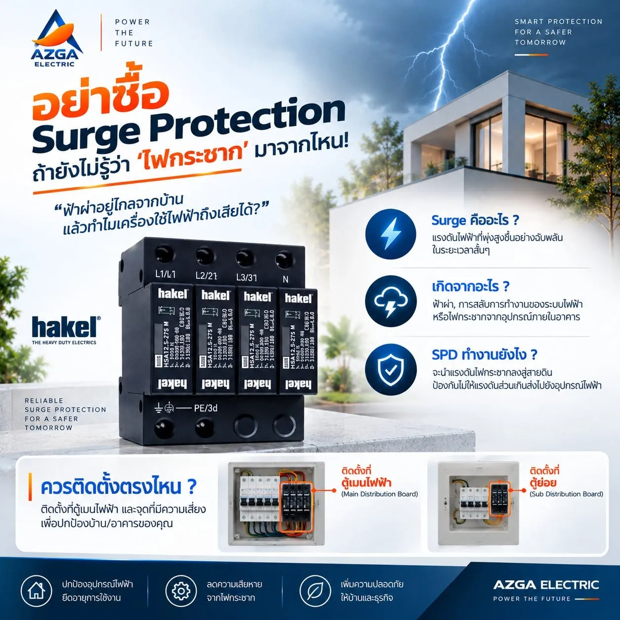
A surge protective device (SPD) is a device installed in an electrical distribution board to limit transient over-voltages and divert surge currents safely to earth. Transient over-voltages last only microseconds, but they can reach several kilovolts — far beyond what electronic equipment such as PLCs, drives, meters and power supplies is designed to withstand.
SPDs for low-voltage power systems are tested according to IEC 61643-11 (EN 61643-11), which defines test classes, ratings and markings.
Where do surges come from?
- Lightning – a direct strike on a building or its lightning protection system, or a strike near overhead lines that induces voltage into the supply.
- Switching operations – switching of large inductive loads such as motors and transformers, capacitor banks or utility network switching.
- Faults on the network – fuse operation and short circuits can create switching transients.
Switching surges are smaller than lightning surges but far more frequent, which is why they gradually degrade sensitive electronics.
How does an SPD work?
Under normal voltage an SPD has a very high impedance and practically no current flows through it. When the voltage rises above its threshold, the protective component — a metal-oxide varistor (MOV), a spark gap or a gas discharge tube (GDT) — switches to a low impedance within nanoseconds and conducts the surge current to the earthing system. Once the surge has passed, the SPD returns to its high-impedance state.
The voltage that remains across the protected equipment during this event is the voltage protection level (Up). A lower Up means better protection, provided it is coordinated with the impulse withstand voltage of the equipment.
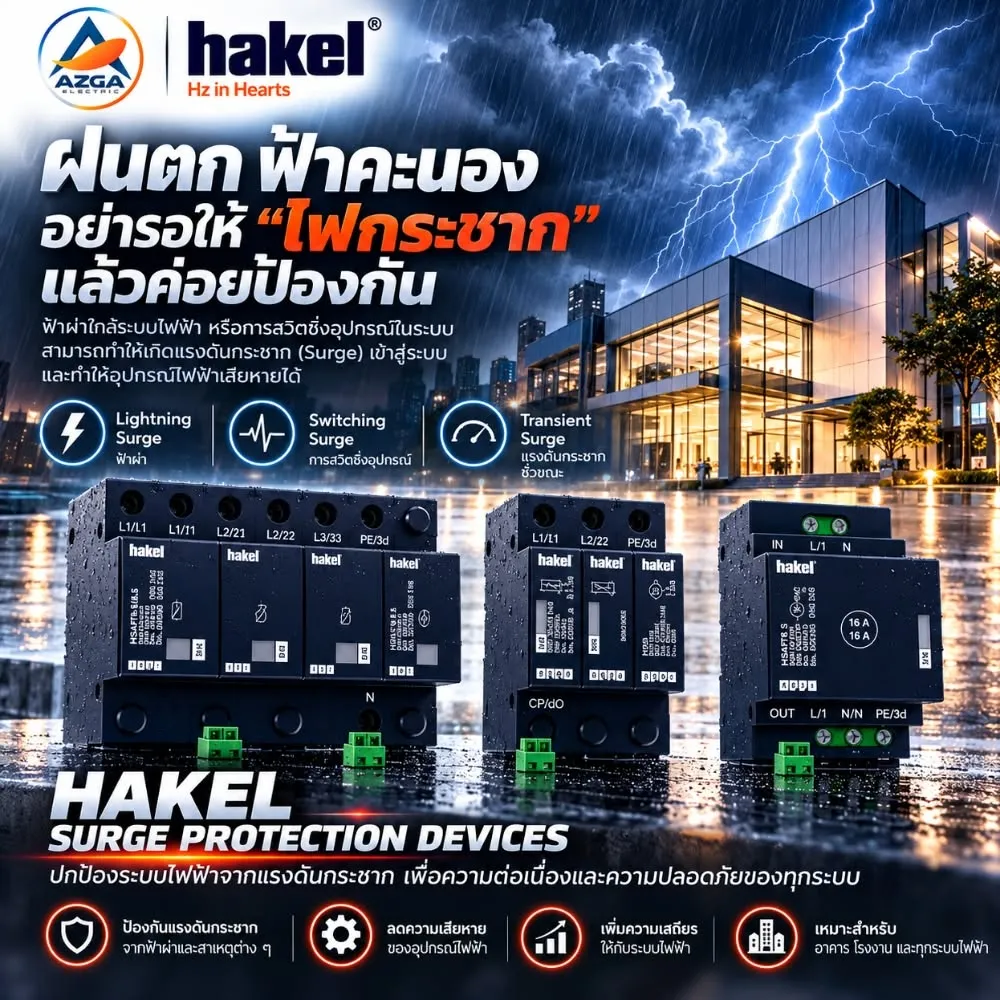
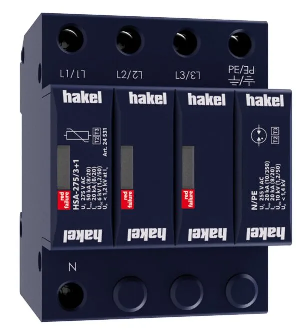
Example from our catalog: the Hakel HSA-275 M S Type 2+3 arrester lists a maximum continuous operating voltage Uc of 275 V, a maximum discharge current Imax of 50 kA (8/20) and a voltage protection level Up < 1.25 kV.
Key ratings to check
| Rating | Meaning |
|---|---|
| Uc | Maximum continuous operating voltage the SPD can withstand permanently. |
| In (8/20 µs) | Nominal discharge current the SPD can conduct repeatedly (Type 2 test). |
| Imax (8/20 µs) | Maximum discharge current for a single impulse. |
| Iimp (10/350 µs) | Impulse current representing partial lightning current (Type 1 test). |
| Up | Voltage protection level – the residual voltage across the terminals. |
| Back-up fuse | Maximum upstream overcurrent protection specified by the manufacturer. |
Installation essentials
- Keep connecting leads as short and straight as possible – long leads add voltage and reduce the effective protection.
- Use the back-up fuse or breaker rating given in the SPD datasheet.
- Choose the configuration (1+1, 3+0, 3+1, 4+0) that matches the earthing system (TN-C, TN-S, TT).
- Prefer devices with a status indicator and a remote signalling contact (often marked “S”) so a worn module can be replaced before protection is lost.
An SPD reduces the risk of damage from transient over-voltage; it does not guarantee protection against every event, and it is part of an overall protection concept together with proper earthing and bonding.
Frequently asked questions
Does an SPD replace a circuit breaker or RCD?
No. An SPD limits short-duration over-voltages. Overcurrent protection (MCB/fuse) and earth-leakage protection (RCD) are still required.
How do I know when an SPD needs replacing?
Many SPDs have a visual indicator that changes colour when the protective module reaches end of life; versions with a remote signalling contact can report this to a PLC or alarm.
Is one SPD at the main board enough?
Often not. Long cable runs and sensitive loads usually require coordinated protection: Type 1 or 1+2 at the service entrance, Type 2 at sub-boards and Type 3 close to sensitive equipment.
Sample article for the prototype — content to be reviewed by the AZGA technical team before publishing.
Need help applying this to your project?