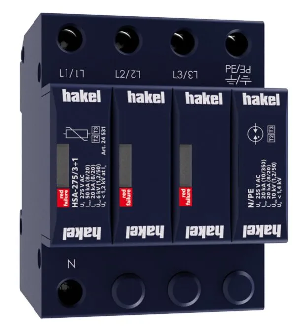
SPD Type 2+3
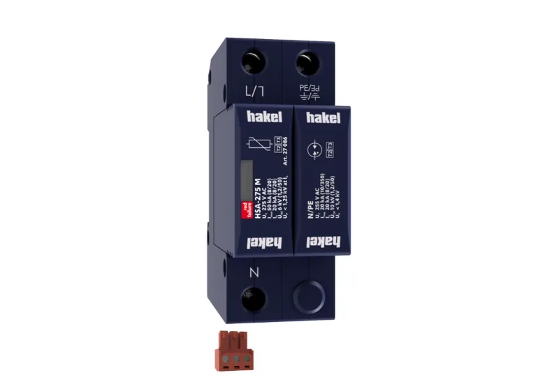
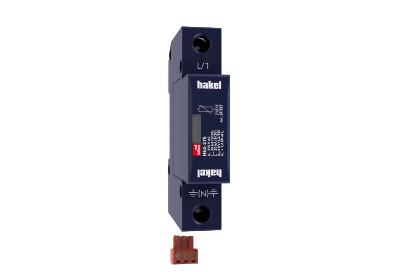
HSA-275 M S
Surge Arrester – Type 2+3 (Class II+III), 1 Pole
- Class
- Type 2+3 (Class II+III)
- Uc
- 275 V
 Click to zoom
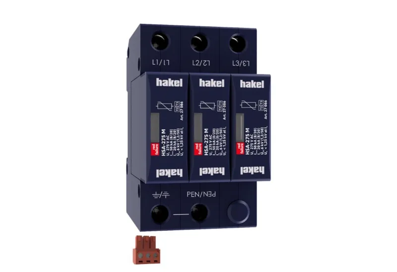
Surge Arrester – Type 2+3 (Class II+III), 3+0 (3 Poles)
HSA-275/3+0 M S (Surge Arrester) : TYPE 2+3, CLASS II+III , 3 Poles
Key specifications
Prefer to talk? Call 02 194 0672
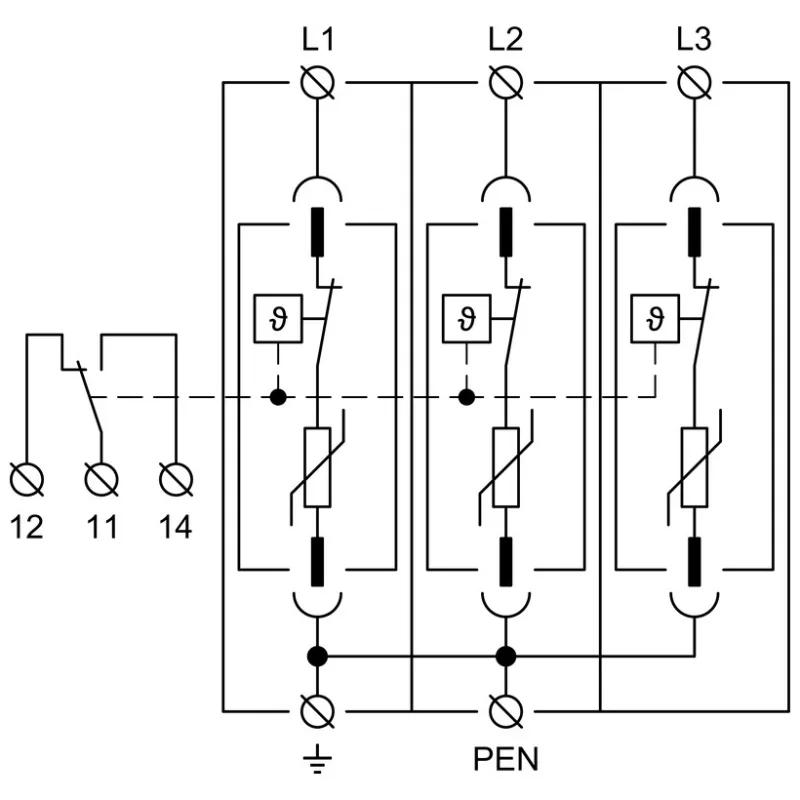
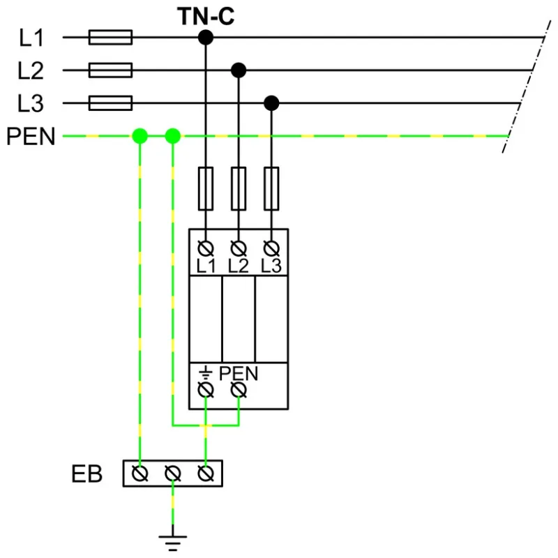
(Hakel Surge Arrester) of the „G-Line“ range is a surge arrester according to EN 61643-11:2012 (IEC 61643-11:2011) consisting of high energy varistors. Its parameters enable its use in complex circumstances. The device is to be installed on the interface of LPZ 1 – LPZ 2 and higher zones according to standard EN 62305:2011 (IEC 62305:2010), i.e. into subsidiary switchboards and control boxes. Surge arresters type T2+T3 ensure the equipotential bonding and reduce switching, induced and residual overvoltage in LV power supply systems. The products consist of varistors with big discharge ability. Configurations 1+1 and 3+1 are additionally combined with a gas discharge tube which ensures zero leakage current through the PE conductor. Installed at the boundaries of LPZ 1 – LPZ 3 into subsidiary switchboards and control panels. If the product contains two PE (or PEN) terminals, it must not be used as a PE (PEN) bridge. M indication specifies a type of construction with removable module. S indication specifies a version with remote monitoring.
| Test class according to EN 61643-11:2012 (IEC 61643-11:2011) | T2, T3 |
|---|---|
| System | TN-C |
| Number of poles | 3 |
| Rated operating AC voltageUN | 230 V |
| Maximum continuous operating voltage ACUC | 275 V |
| Maximum discharge current (8/20)Imax | 50 kA |
| Nominal discharge current for class II test (8/20)In | 20 kA |
| Open circuit voltage of the combination wave generatorUOC | 6 kV |
| Total discharge current (8/20) L1+L2+L3->PENITotal | 150 kA |
| Voltage protection level at InUp | < 1.25 kV |
| Voltage protection level at UOCUp | < 0.85 kV |
| Temporary overvoltage test (TOV) for tT = 5 sUT | 337 V |
| Temporary overvoltage test (TOV) for tT = 120 minUT | 440 V |
| Response timetA | < 25 ns |
| Maximal back-up fuse | 160 A gL/gG |
| Residual currentIPE | ≤ 200 µA |
| Short-circuit current rating at maximum back-up fuseISCCR | 60 kArms |
| Lightning protection zone | LPZ1, LPZ2, LPZ3 |
| Housing material | Polyamid PA6, UL94 V-0 |
| Degree of protection | IP20 |
| Operating temperatureϑ | - 40 ÷ 70 °C |
| Humidity rangeRH | 5 ÷ 95 % |
| Minimum cross-section of connected Cu conductors accord. to HD 60364-5-534:2016 (doesn't apply to „V“ connection) for T2S | 2.5 mm² (L, N) |
| Clamp fastening range (solid conductor) | 1.5 ÷ 25 mm2 |
| Clamp fastening range (stranded conductor) | 1.5 ÷ 16 mm2 |
| Tightening moment | 3 |
| Installation | On DIN rail 35 mm |
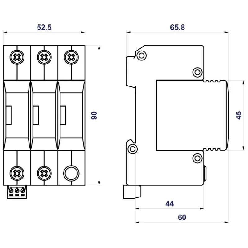
| Modular width | 3 |
| Operating position | Any |
| Product placement environment | Internal |
| Signalling at the device | Optic |
| Importance of local signaling | OK – clear target |
| Remote signalling | Yes |
| Potential free signal contact (S) (recommended cross-section of remote monitoring max. 1 mm2) | AC: 250 V / 1.5 A, DC: 250 V / 0.1 A |
| Modular design | Yes |
| Article number of spare module | 27 086 |
| Lifetime | > 100 000 h |
| Protection against lightning | IEC 62305:2010 |
| Selection and erection of electrical equipment – Devices for protection against transient overvoltages | HD 60364-5-534:2016 |
| Selection and application principles for SPDs connected to low-voltage power systems | CLC/TS 61643-12:2009 |
| Requirements and test methods for SPDs connected to low-voltage power systems | IEC 61643-11:2011 |
| Safety of Flammability of Plastic Materials | UL 94 |
SPD Type 2+3
Surge Arrester – Type 2+3 (Class II+III), 1 Pole
SPD Type 2+3
Surge Arrester – Type 2+3 (Class II+III), 1+1 (2 Pole)
SPD Type 2+3
Surge Arrester – Type 2+3 (Class II+III), 3+1 (4 Poles)
SPD Type 2+3
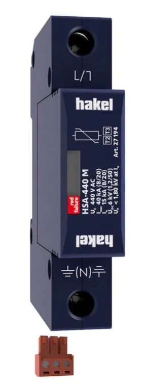
Surge Arrester – Type 2+3 (Class II+III), 1 Pole 440 V AC
Send us your quantities and requirements — our team will reply with a quotation.