
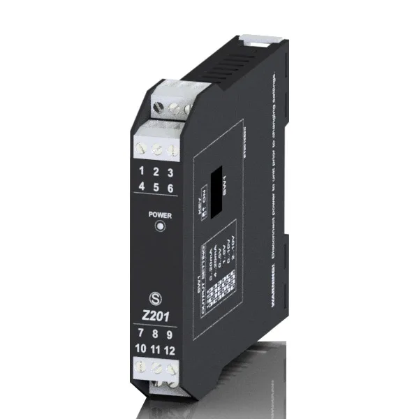
What is a relay interface module?
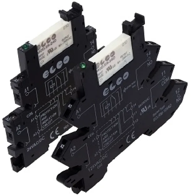
A relay interface module is a relay mounted on a DIN-rail socket with coil protection, status LED and screw or spring terminals. It sits between a PLC or controller and the field device, providing galvanic isolation, higher switching capacity and easy replacement. Slim 6.2 mm modules such as the Elco ECLR series save rail space and support jumper combs for common connections.
Electromechanical vs solid state
| Electromechanical (ECLR) | Solid state (EZD-ECLR) | |
|---|---|---|
| Switching | Mechanical contact, AC or DC loads | Semiconductor, no moving parts |
| Life | Limited by contact wear | Very high switching frequency possible |
| Typical use | Contactors, valves, signal lamps | Fast cycling, silent operation, DC loads |
Selection tips
- Match the input voltage (e.g. 24 V AC/DC or 240 V AC/DC on ECLR models).
- Check output current and load type – 6 A for ECLR; SSR outputs have specific voltage/current ranges.
- Choose screw or spring-cage connection to suit your wiring standard.
Frequently asked questions
Why not switch the load directly from the PLC output?
An interface relay protects the PLC output from inductive spikes and overload, isolates field wiring and is quick to replace if a contact wears out.
Sample article for the prototype — content to be reviewed by the AZGA technical team before publishing.
Need help applying this to your project?